FROM A TO Z

The dictionary for communication between SCADA systems, controllers, other electrical devices and people. All entries from A to Z.

A
ARP — Address Resolution Protocol
The Address Resolution Protocol (ARP) is a communication protocol used for discovering the link layer address (e.g. MAC address) that is associated with a given internet layer address, commonly IPv4.
The mapping function provided by ARP is critical to the Internet protocol suite and has been implemented with many combinations of network and data link layer technologies, such as IPv4, Chaosnet and DECnet using IEEE 802 standards, FDDI, X.25 and Frame Relay amongst others.
C
COMTRADE file — IEEE C37.111‑1999
The Comtrade file contains time-stamped voltage and current samples that represent the behavior of the power system during a disturbance. The data is typically captured by protective relays or other monitoring equipment and is used to analyze and diagnose faults and disturbances in the power system.
The Comtrade file format was developed by the Institute of Electrical and Electronics Engineers (IEEE) and is widely used in the power industry. It provides a standardized way to exchange data between different manufacturers’ equipment and allows for easier data analysis and comparison across different power systems.
D
DLMS
DLMS/COSEM (or IEC 62056) is the main global standard for smart energy metering, control and management. It includes specifications for media-specific communication profiles, an object-oriented data model and an application layer protocol.
DNP3.0
Distributed Network Protocol 3 (DNP3) is a set of communications protocols used between components for automation systems in electric, industrial and water sectors.
It is a key protocol in SCADA systems, where it is primarily used for communications between a master station and RTUs or IEDs.
E
eIoT — Energy IoT
EThe Energy IoT (eIoT) is a rapidly growing area of IoT (Internet of Things) that focuses on the use of connected devices and sensors to improve energy efficiency, reduce waste, and promote sustainability in the energy sector. The eIoT encompasses a wide range of technologies and applications, including smart grids, smart homes, smart buildings, and industrial IoT.
One of the key benefits of the eIoT is its ability to provide real-time data and insights about energy consumption and production. By collecting data from connected devices and sensors, energy companies can gain a better understanding of how energy is being used and where there may be opportunities for improvement. This can help to reduce waste, lower costs, and improve the reliability and resilience of energy systems.
The eIoT can also help to promote the use of renewable energy sources, such as solar and wind power. By using connected devices and sensors to monitor energy production and consumption, energy companies can better integrate renewable energy sources into the grid and optimize their use.
In addition to its benefits for energy companies, the eIoT can also have significant benefits for consumers. By using connected devices and sensors in homes and buildings, consumers can gain greater control over their energy usage and reduce their energy bills. For example, smart thermostats can automatically adjust the temperature of a home or building based on occupancy and weather conditions, reducing energy waste and improving comfort.
Encryption
Encryption, from ancient Greek Kryptós (“hidden”), is the art of hiding written messages by applying a given mathematical algorithm. Encryption seeks many objectives, such as;
- Confidentiality: the original message (“plain text”) should not be understood by anybody else than the legitimate destination
- Authentication; the receiver wants to make sure that the message comes from an authorised source. This is important, for example in a GOOSE message tripping a breaker (who sent it? Is the transmitter really authorised to trip a breaker or not?)
- Integrity: the receiver wants to make sure that the original message has not been modified by a man-in-the-middle attack
All encryption algorithms can be classified under the following two categories;
- Symmetrical encryption
- Asymmetrical encryption
Encryption for Smart Grids is defined in IEC62351 series (Substations), IEC 62056 (Smart Meters) and NERC-CIP, among others. Usually a combination of asymmetrical and symmetrical algorithms is used to benefit from the advantages of both categories.
ESS — Energy Storage System
An energy storage system (ESS) is a technology that is designed to store energy and release it when it is needed. ESSs are becoming increasingly important as renewable energy sources, such as solar and wind power, become more widely used. These sources of energy are intermittent, meaning that they can’t always generate electricity when it is needed. ESSs can help to balance the supply and demand of electricity by storing excess energy when it is generated and releasing it when it is needed.
One of the most known methods is battery storage, which involves storing electrical energy in batteries, which can be charged and discharged as needed. Battery storage systems can be used in homes, businesses, and utility-scale applications.
Ethernet
Ethernet is a family of wired computer networking technologies commonly used in local area networks (LAN) and also wide area networks (WAN).
Over time, Ethernet has largely replaced competing wired LAN technologies by providing higher bit rates, a greater number of nodes, and longer link distances and decent backward compatibility.
F
100BASE-TX — Fast Ethernet
100BASE-TX is the most common Fast Ethernet physical layer, transmitting data through two twisted wire-pairs (one for each direction), which provide full duplex operation with 100 Mbit/s of throughput in each direction.
The cabling distance is limited to 100 metres (328 ft) for each network segment.
FTP — File Transfer Protocol
The File Transfer Protocol (FTP) standard defines an application layer network protocol to transfer files from a server to a client on a computer network.
FTP is based on a client-server model architecture using separate control and data connections between client and server.
FX100 Ethernet
Fast Ethernet is the name of the extension to 100 Mbit/s Ethernet network to 10 Mbit/s. This is the IEEE 802.3u working group that is at the origin. Access technique is the same as in the Ethernet Version 10 Mbit/s, but at a speed multiplied by 10. transported frames are identical. This increase in speed may conflict with the wiring system and the possibility or not there such important transit flows.
G
Gateway
A communication gateway is a hardware or software device that serves as an intermediary between different communication protocols, allowing them to exchange information and data. Its primary function is to enable interoperability and seamless communication between disparate systems that may use different communication protocols, data formats, or technologies.
In substation automation is very common the use of gateways to collect information from IEDs and send it to the control center or the site RTU
Grid Codes
Grid codes are a set of technical requirements and standards that govern the operation and interconnection of power generation and distribution systems to the electric grid. Grid codes are developed and enforced by regulatory authorities and system operators to ensure the safe, reliable, and efficient operation of the power system.
Grid codes typically cover a wide range of technical aspects related to the connection and operation of power generation and distribution systems, including:
-
Power quality: Grid codes define the minimum standards for voltage and frequency stability, harmonics, and other parameters that affect the quality of the power supplied to the grid.
-
Protection: Grid codes specify the protection schemes and settings required to ensure the safe and reliable operation of the power system, including measures to prevent faults and protect equipment from damage.
-
Control and monitoring: Grid codes require the use of specific control and monitoring systems to ensure the stability and reliability of the power system, including the use of automatic generation control (AGC), frequency control, and other measures.
-
Connection requirements: Grid codes specify the technical requirements for connecting power generation and distribution systems to the grid, including the requirements for equipment, protection, and control systems.
Grid codes are important for ensuring the safe and reliable operation of the power system, and for enabling the integration of renewable energy sources and other distributed generation systems. Compliance with grid codes is typically mandatory for all power generation and distribution systems connected to the grid.
H
HTTP — Hypertext Transfer Protocol
The Hypertext Transfer Protocol (HTTP) is a standardized application layer protocol for distributed and collaborative, hypermedia information systems.
Alongside HTML, HTTP facilitated the development of original World Wide Web, the first interactive, text-based web browser.
HTTPS — Hypertext Transfer Protocol Secure
HTTPS (Secure HTTP) is the cybersecured version of HTTP, Hyper Text Transfer Protocol. Its purpose is to encrypt the contents of a web page so that its transmission between client and server benefits from confidentiality, authentication and integrity. In fact HTTPS is HTTP (Application Layer) combined with TLS (Transport Layer Security), an encryption layer that makes uses of encryption algorithms.
HSR — High-availability Seamless Redundancy
Unlike common redundancy protocols like RSTP, HSR reacts to any network component failures seamlessly (without recovery time) and is invisible to the application.
I
ICCP/ TASE.2
ICCP (Inter-Control Center Communications Protocol) is a standard protocol for communications between control centers, which is part of the IEC 60870–6 standard under the name of TASE.2 Telecontrol Application Service Element 2.
It is being used around the world to exchange data over wide area networks (WANs) between grid operators, utilities, virtual power plants, regional control centers and other generators.
IEC 60870–5‑104 // IEC104
IEC 60870–5 is a protocol standard for telecontrol, teleprotection, and other telecommunication functions for electric power systems.
IEC 60870–5‑104 (short IEC-104) is a companion standard defining how to extend the IEC 60870–5‑101 protocol to gain network access using standard transport profiles.
IEC 60870–5‑101/104 DPS — Double Point State
DPS, or Double Point State, is a data type defined in the IEC 60870–5‑104 communication protocol, which is used for exchanging data between supervisory control and data acquisition (SCADA) systems and remote terminal units (RTUs) or intelligent electronic devices (IEDs).
In IEC 60870–5‑104, DPS is used to represent the status of a binary signal, such as a switch or valve, that can be in one of two possible states: ON or OFF. DPS uses two bits to represent each binary signal, allowing for four possible states: ON, OFF, Indeterminate, or Error.
The four possible states of DPS are defined as follows:
- ON: The binary signal is in the ON state.
- OFF: The binary signal is in the OFF state.
- Indeterminate: The status of the binary signal is uncertain or undefined.
- Error: An error condition has occurred while reading or writing the binary signal.
DPS is commonly used in SCADA systems and other industrial applications to monitor and control the status of binary signals in remote devices. The use of DPS in IEC 60870–5‑104 ensures that the status of binary signals can be accurately and reliably communicated between SCADA systems and RTUs or IEDs, allowing for effective control and monitoring of industrial processes.
IEC 61850 — BRCB/URCB — Buffered/Unbuffered MMS Reports
IEC 61850 distinguishes between buffered and unbuffered reporting. In unbuffered reporting events will not be logged and reported if the associated client for the unbuffered report control block is not connected. In the case of buffered reporting the events will be logged for a specific amount of time and sent later when the client is connected again
IEC 61850 — GOOSE
The GOOSE (Generic Object Oriented Substation Event) protocol is a communication model defined by the IEC 61850 standard, which uses fast and reliable mechanisms to group any format of data (status, value) into a data set and transmit it through electrical networks within 4 milliseconds.
It is most commonly used for data exchanges between IEDs (IED – Intelligent Electronic Device) in electrical substations over Ethernet.
IEC 61850 — ICD File
IED Capability Description (ICD) files are a specific type of Substation Configuration Language (SCL) file, containing a generic description of the whole capability range of a given device, including the functions and objects it can support.
The ICD file is usually supplied by the developer/manufacturer.
IEC 61850 — LN Logical Node
Logical nodes or LN (abstract data objects) are the main elements of the virtual object-oriented IEC 61850 model, which consists of standardized data and data attributes.
The abstract data objects can be mapped to any other protocol, as for example with the MMS or SMV protocol on an Ethernet data frame.
IEC 61850 — MMS Protocol
IEC 61850 MMS (Manufacturing Message Specification) is a client/server based protocol for communications between IEDs (IED – Intelligent Electronic Device) and higher level entities (such as RTUs and SCADAs) over Ethernet that is part of the IEC 61850 standard for communication technology in substations.
It is mapped onto TCP/IP and allows to access the server through its IP address in order to write/read data and exchange files.
IEC 61850 — SCL — Substation Configuration Language
The IEC 61850 standard for substation automation specifies a stadardized substation configuration language (SCL) to transfer device descriptions and communication parameters amongst different vendors/manufacturers.
SCL files define several capability subsets for the IED to instantiate its capabilities.
IEC 62439–3
IEC 62439–3:2016 defines the PRP and HSR standards, which provide seamless failover against failure of any single component in Ethernet networks.
PRP and HSR are application protocol independent, can be used by most Industrial Ethernet protocols in the IEC 61784 suite and have been integrated in the framework of IEC 61850 for substation automation.
IEC 62443
IEC 62443 is an International Standard dealing with cybersecurity in Industrial Automation and Control Systems (IACS). While IEC 62351 emphasizes on encrypting communications, IEC 62443 emphasizes on the device itself and introduces requirements such as a generalised definition of user (so that RBAC applies not only to humans but software processes as well); or the requirement that passwords be stored in hardware, which makes the use of TPM ICs necessary. From its very definition IEC 62443 applies naturally to RTUs and associated equipment.
IEC 62439–3
IEC 62439–3:2016 defines the PRP and HSR standards, which provide seamless failover against failure of any single component in Ethernet networks.
PRP and HSR are application protocol independent, can be used by most Industrial Ethernet protocols in the IEC 61784 suite and have been integrated in the framework of IEC 61850 for substation automation.
IEC 62351
IEC 62351 is a series of Standards dealing with Cybersecurity in electricity systems. Developed by IEC TC57 WG15, they aim at improving the different aspects of Cybersecurity in the different RTUs and IEDs deployed in substations, with parts dedicated to encryption and key exchange in telecontrol protocols (e.g. IEC 60870–5‑104 or DNP3.0), 61850, Smart Metering (DLMS-COSEM), RBAC (Role Based Access Control) and Conformance Testing among others.
IED — Intelligent Electronic Device
In the power sector, intelligent electronic devices (IED) are microprocessor based power system equipment, such as circuit breakers, transformers and capacitor banks, providing control and automation functions.
IEDs receive and process data from sensors and other equipment to issue control commands or adjust tap poisitions in order to prevent failures and maintain the desired voltage level.
IP Routing
IP routing encompasses different methodologies to route Internet Protocol (IP) packets within and across IP networks by determining a suitable path to transfer network packets between source and destination nodes in and across IP networks.
IP Routing protocols enable routers to build up a forwarding table that correlates final destinations with next hop addresses.
Interlocking (network protection scheme)
The interlock consists of one or more switches that prevent both main power and generator power from powering the dwelling simultaneously. Without this safeguard, both power sources running at once could cause an overload condition, or generator power back-feed onto the main could cause dangerous voltage to reach a lineman repairing the main feed far outside the building.
Inverter
An inverter is an electronic device that converts direct current (DC) into alternating current (AC). It is widely used in various applications to change the type of electrical power supply..
Inverters play a vital role in enabling the use of alternative energy sources like solar and wind power and are essential in many modern electrical systems.
A string inverter is a type of photovoltaic (PV) inverter used in solar power systems. Its primary function is to convert the direct current (DC) electricity generated by a string of solar panels into alternating current (AC) electricity suitable for use in homes or to feed back into the electrical grid. While string inverters have several advantages, they also have some limitations. The performance of the entire string can be affected if one panel in the string is shaded or underperforming, as the inverter operates at the lowest common denominator. Additionally, their centralized nature can lead to efficiency losses in cases where panels are not optimally oriented or partially shaded.
M
MAC — Medium Access Control
The Medium Access Control (MAC) sublayer provides flow control and multiplexing for the transmission medium to control the hardware that interacts with the wired, optic and also wireless transmission media in the IEEE 802 LAN/MAN data link layer.
The MAC is accompanied by the LLC sublayer, which provides flow control and multiplexing for the logical link (i.e. EtherType, 802.1Q VLAN tag etc.)
Meter or Energy meter
An energy meter, also known as an electricity meter or electric meter, is a device used to measure and record the consumption of electrical energy in a residential, commercial, or industrial facility. These meters are essential for billing purposes, as they determine the amount of electricity consumed by a customer, but also for monitoring and control purposes.
Energy meters are an integral part of the electricity distribution infrastructure, and they play a crucial role in the fair and accurate billing of electricity consumption. The advancement of technology, particularly with the introduction of smart meters, has enabled more efficient and transparent monitoring of electricity usage, benefiting both utility companies and consumers.
Usually, SCADA systems and RTUs connect with energy meter using DLMS and IEC 60870–5‑102 protocols
Modbus RTU & TCP
Modbus is a communications protocol based on master/slave (RTU) or client/server (TCP/IP) architectures that can operate on the 1st, 2nd, 7th level of the OSI Model.
Originally designed in 1979 by Modicon for its range of PLCs, it is now a de facto standard communications protocol in the industry, becomming the most widely available protocol for the connection of industrial electronic devices.
MQTT
MQTT is designed to be simple, efficient, and reliable, making it well-suited for use in resource-constrained environments. It uses a small message header, which minimizes the amount of data that needs to be transmitted, and it also includes features such as Quality of Service (QoS) levels, which provide different levels of reliability for message delivery.
MQTT supports a wide range of applications, including home automation, industrial control systems, and telemetry applications. It is used by many IoT platforms and is supported by a wide range of programming languages and platforms, making it a popular choice for building IoT applications.
Overall, MQTT is a flexible and reliable messaging protocol that is well-suited for use in IoT and other applications that require efficient and reliable messaging in constrained or low-bandwidth networks.
Multi-drop Bus
In order to automate, monitor and control a substation and its intelligent devices in real time from a central monitoring station, the substation must be connected to a Supervisory Control and Data Acquisition (SCADA) system.
The SCADA provides grid operators with an HMI (Human Machine Interface) to visualize collected data and facilitate the substation maintenance and operation.
N
NERC CIP
North American Electricity Reliability Corporation (NERC), and its predecesor North American Electricity Reliability Council, is a non-profit organisation whose goal is to ensure the reliability of electricity supply across North America by developing technical standards for power system operation. NERC developed the so-called CIP (Critical Infrastructure Protection), a set of nine standards to implement cybersecurity in power systems. NERC-CIP standards cover technical and non-technical aspects, such as the use of encryption or personnel awareness and training, and have been adopted worlwide as a reference framework for cybersecurity in power systems.
Network Redundancy
Network redundancy is a method to ensure network availability, providing failover when a device or network path fails or becomes unavailable.
Redundancy is usually achieved by installing additional or alternative network devices, communication media or equipment within the network infrastructure.
NTP — Network Time Protocol
NTP stands for Network Time Protocol, which is a protocol used to synchronize the clocks of networked devices over the Internet or other networks.
NTP is designed to provide accurate and reliable time synchronization for a wide range of applications, including industrial control and other time-sensitive systems. NTP works by exchanging time synchronization messages between devices, using a hierarchical system of time servers to ensure accuracy and reliability.
NTP is widely used across the Internet and other networks to synchronize the clocks of devices with a reference time source, such as an atomic clock or GPS receiver. This allows devices to maintain accurate and consistent time, even in the face of network delays and other factors that can affect clock accuracy.
NTP is a key component of many modern computer systems and networks, and is often used in conjunction with other time synchronization protocols and technologies to provide a reliable and accurate time source for critical applications.
P
PKI — Public Key Infrastructure
PKI stands for Public Key Infrastructure, which is a set of technologies, processes, and policies used to manage digital certificates and public-key encryption. A PKI enables secure communication over untrusted networks by providing a framework for verifying the identity of users, devices, and servers, and for ensuring the confidentiality, integrity, and authenticity of information exchanged over the network.
A PKI typically consists of several components, including:
- Certificate Authority (CA): A trusted third-party that issues digital certificates to users and devices, which are used to authenticate their identity and establish secure communication.
- Registration Authority (RA): A component that verifies the identity of users and devices before issuing digital certificates.
- Certificate Repository: A database or directory that stores digital certificates issued by the CA.
- Certificate Revocation List (CRL): A list of digital certificates that have been revoked or are no longer valid.
- Certificate Policy: A set of rules and guidelines that govern the issuance and management of digital certificates within the PKI.
A PKI is widely used in many applications and industries, including power control, e‑commerce, online banking, and secure email. PKI provides a secure and reliable method for verifying the identity of users and devices, and for protecting sensitive information from unauthorized access or interception.
PLC — IEC 61131–3
IEC 61131 is an international standard that describes Programmable Logic Controllers, a type of programmable industrial automation systems. IEC 61131 PLC systems embedded in RTUs allow the implementation of custom functions by processing different inputs and generating outputs.
Common examples are an RTU automatically connecting capacitor banks when the reactive power exceeds a threshold or performing load shedding when the frequency deviates. The program itself can be written in five different programming languages, described in part 3 of the standard.
PLC according to IEC61131‑3 is supported in all iGrid products, including the iRTU/iGW series and the iControl SCADA system.
Power Plant Controller — PPC
PPC (Power Plant Controller) is a control loop that regulates the amount of energy injected to the grid by a generation plant, to make sure that complies with both the setpoints and the grid codes dictated by the TSO. The PPC receives the setpoint from the TSO delegate office and receives feedback from a meter installed at the Point of Injection.
Profibus
PROFIBUS (Process Field Bus) is an open standard for fieldbus communications in industrial automation systems that was first promoted in Germany in 1989.
The now most commonly found “Profibus DP” provides simple communications between Profibus masters and their remote I/O slaves.
Protection Relay
A protection relay is an electronic device which constitutes an an essential component in electrical power systems, being designed to detect abnormal operating conditions or faults in the power system and initiate appropriate actions to protect the equipment and ensure the safety and stability of the electrical network.
The main function of a protection relay is to monitor electrical parameters such as current, voltage, frequency, power, and other relevant quantities within the power system. When the relay detects a fault or abnormal condition, it sends a signal to the associated circuit breaker or other switching devices to isolate the faulty section from the rest of the network.
Here are some key features and functions of a protection relay:
- Fault Detection: Protection relays continuously monitor the electrical parameters of the power system. They analyze these parameters and compare them to predefined settings to identify abnormal conditions, such as short circuits, overloads, voltage sags, overvoltage, underfrequency, and other faults. The functions executed by the protection relays are defined by standarization bodies, like IEEE with its standard IEEE C37.2
- Selectivity and Coordination: Protection relays are designed to provide selectivity and coordination in the electrical network. Selectivity ensures that only the closest circuit breaker to the fault location is tripped, minimizing the impact on the rest of the system. Coordination allows for sequential operation of relays and circuit breakers to isolate faults in a cascading manner.
- Relay Logic and Algorithms: Protection relays employ various logic schemes and algorithms to determine fault conditions accurately and reliably. These schemes may include time-based, current-based, or voltage-based techniques to differentiate between fault and normal operating conditions.
- Communication and Integration: Modern protection relays often feature communication capabilities, enabling them to exchange information with other relays, control systems, and monitoring devices, with communication protocols like IEC 61850, DNP3.0 or IEC 60870–5‑103. This facilitates remote monitoring, centralized control, and coordinated protection across different parts of the power system.
PRP — Parallel Redundancy Protocol
PRP (Parallel Redundancy Protocol) is a redundancy protocol for Ethernet based networks requiring high availability and a short switchover time, as for example protection systems at electrical substations.
Unlike common redundancy protocols like RSTP, PRP reacts to any network component failures seamlessly (without recovery time) and is invisible to the application.
PTP — Precision Time Protocol — IEEE 1588
IEEE 1588 is a standard for precision clock synchronization of networked devices. It is also known as Precision Time Protocol (PTP).
The IEEE 1588 standard provides a mechanism for synchronizing the clocks of devices connected over a network with sub-microsecond accuracy. This is particularly important in applications such as industrial automation, financial trading, telecommunications, and other real-time systems where accurate timing is critical.
The standard defines a protocol that enables devices to synchronize their clocks to a common reference time, known as a grandmaster clock. This is achieved by exchanging timing messages between devices over the network, and adjusting the local clock of each device to align with the grandmaster clock.
IEEE 1588 has several different profiles, each tailored to specific applications and network topologies. It is widely used in industrial control systems, power distribution networks, and other critical infrastructure applications.
PV plant Performance Ratio
The performance ratio (PR) is a metric used to evaluate the efficiency and performance of a photovoltaic (PV) power plant. It represents the ratio of the actual energy output of the PV system to the theoretical or expected energy output under standard test conditions (STC). The performance ratio is expressed as a percentage.
The performance ratio takes into account various factors that affect the energy production of a PV plant, including system losses, environmental conditions, and equipment performance. It provides a measure of how effectively the PV system converts sunlight into usable electricity.
The International Electrotechnical Commission (IEC) defines the IEC 61724 standard which outlines the procedures and guidelines for the assessment of the energy yield of PV systems. This standard provides a framework for measuring, calculating, and reporting the performance ratio of a PV plant. It’s worth noting that the exact calculation methodology and parameters for determining the performance ratio may vary slightly based on project-specific requirements and local regulations. However, the IEC 61724 standard provides a widely accepted framework for performance ratio assessment in the PV industry.
The performance ratio calculation considers several factors, including:
1. System losses: These losses include electrical losses, such as wiring and inverter losses, as well as losses due to shading, soiling, and mismatch between PV modules.
2. Temperature losses: PV modules experience reduced efficiency as their temperature increases. Temperature losses account for the decrease in performance due to higher module temperatures.
3. Irradiance losses: The actual solar irradiance received by the PV modules may deviate from the reference conditions assumed during the performance estimation. Irradiance losses account for the deviation between the actual and reference irradiance levels.
By considering these factors, the performance ratio provides an assessment of the overall performance and efficiency of the PV system, taking into account real-world conditions and losses. A higher performance ratio indicates better performance and efficiency of the PV plant.
R
RBAC — Role Based Access Control
RBAC, or role-based access control, is a method of restricting access to resources based on the roles of individual users within an organization. In the context of IEC 62351, which is a standard for secure communication between control systems in the power industry, RBAC is used to ensure that only authorized users are able to access critical systems and data.
IEC 62351 defines a set of security mechanisms for protecting communication in power systems, including RBAC. In this standard, RBAC is implemented through the use of roles, which are defined based on the functions that users perform within an organization. Each role is associated with a set of permissions that dictate what actions a user with that role is allowed to perform.
For example, in a power system, there might be roles for system administrators, operators, and engineers. The system administrator role might have permission to modify system configurations, while the operator role might only be able to view system status and perform basic operations. By using RBAC, organizations can ensure that users only have access to the resources and data that they need to perform their specific job functions, while also minimizing the risk of unauthorized access or data breaches.
RMU — Ring Main Unit
A Ring Main Unit (RMU) is a type of compact switchgear used in electrical distribution systems. It is typically used in medium-voltage power distribution networks, such as in industrial plants, commercial buildings, and residential areas.
The primary purpose of an RMU is to control and protect the distribution of electrical power within a ring circuit, and they have a crucial role in maintaining the reliability and efficiency of medium-voltage power distribution by providing switching, protection, and control functionalities in a compact and modular form.
Here are some key features and functions of an RMU:
- Compact Design: RMUs are designed to be compact, allowing for easy installation in space-constrained areas.
- Ring Circuit Configuration: RMUs are used in ring distribution networks where power flows in a looped configuration. This design provides redundancy and improves the reliability of the distribution system.
- Switching and Protection: RMUs consist of multiple switching devices, such as circuit breakers and load break switches. These devices enable the isolation, switching, and protection of different sections of the distribution network.
- Fault Detection and Restoration: RMUs are equipped with monitoring and control capabilities to detect faults, such as short circuits or overloads. When a fault occurs, the RMU can isolate the affected section of the network and restore power to the remaining sections.
- Voltage Regulation: Some RMUs also incorporate voltage regulation capabilities to ensure a stable supply of electrical power within the distribution network.
- Remote Monitoring and Control: Advanced RMUs may have built-in communication capabilities, allowing for remote monitoring, control, and automation of the distribution system.
RS-232 — TIA/EIA-232
The RS-232 (Recommended Standard-232) or also known EIA-232 (Electronic Industries Alliance-232) is a standard for the serial transmission of data in industrial applications.
The standard defines the electrical characteristics and timing of signals, the meaning of signals, and the physical size and pinout of connectors.
RS-422 — TIA/EIA-422
The RS-422 (Recommended Standard-422) or also known EIA-422 (Electronic Industries Alliance-422) standard defines the characteristics of an electrical interface for serial communications in industrial control systems.
It was designed to replace the older RS-232C standard in order to provide higher speed (up to 10 Mb/s), better immunity from noise, and longer cable lengths (up to 1,500 meters).
RS-485 — TIA/EIA-485
The RS-485 (Recommended Standard-485) or also known EIA-485 (Electronic Industries Alliance-485) standard defines the characteristics of an electrical interface for serial communications in industrial control systems.
In contrast to the older RS-232, it allows to balance electrical signals and connect multiple device to the network, which can stretch over longer distances and harsher environments.
RSTP
RSTP stands for “Rapid Spanning Tree Protocol.” It is a network protocol used in Ethernet networks to prevent loops in the network topology and ensure that data is forwarded along the most efficient path. RSTP is an improvement over the original Spanning Tree Protocol (STP) and offers faster convergence times, making it more suitable for modern networks where rapid changes in the network topology can occur.
Here are the key features and characteristics of RSTP:
-
Loop Prevention: RSTP’s primary function is to prevent loops in Ethernet networks. Loops can lead to broadcast storms and network instability, so RSTP ensures that there is a loop-free path in the network by selectively blocking certain network links.
-
Faster Convergence: One of the significant improvements of RSTP over STP is its ability to converge quickly when there are changes in the network topology. Traditional STP can take several seconds to several minutes to reconfigure after a link failure or network change, while RSTP typically converges in just a few seconds.
-
Port Roles: RSTP defines different roles for network ports, including Root, Designated, Alternate, and Backup ports. These roles determine which ports are actively forwarding traffic and which are in standby mode, ready to take over if a failure occurs.
-
Bridge Protocol Data Units (BPDU): RSTP uses BPDU messages to exchange information between switches in the network. These messages are used to elect a Root Bridge (the central switch in the spanning tree) and determine the best path to reach the Root Bridge.
-
Port States: RSTP defines several port states, including:
- Blocking: Ports in this state do not forward traffic but listen to BPDU messages to determine the network topology.
- Listening: Ports in this state are transitioning to the Forwarding state. They still do not forward data frames but listen for potential network changes.
- Learning: Ports in this state continue to listen for network changes and also learn MAC addresses from incoming frames.
- Forwarding: Ports in this state actively forward data frames.
-
Topology Changes: RSTP is designed to react quickly to changes in the network, such as link failures or additions. When a topology change occurs, RSTP recalculates the spanning tree and converges rapidly to a new stable state.
-
Compatibility: RSTP is backward compatible with STP. It can operate in a mixed network where some switches are running traditional STP while others are running RSTP.
-
802.1Q VLANs: RSTP is often used in conjunction with VLANs (Virtual LANs) to create separate broadcast domains within a single physical network. RSTP can work with 802.1Q VLAN tagging to ensure loop-free topologies within each VLAN.
RSTP has become the preferred choice for loop prevention and network stability in Ethernet networks due to its faster convergence times and improved efficiency compared to traditional STP. It is widely used in modern networking equipment and is considered a standard protocol for managing network topologies in Ethernet-based LANs.
RTU — Remote Terminal Unit
RTU most commonly stands for Remote Terminal Unit, but is sometimes also used as an abbreviation for Remote Telemetry Unit or Remote Telecontrol Unit.
RTUs are devices that rely on microprocessors and communication interfaces to automatically monitor and control field devices and establish a bridge to the plant control or SCADA (supervisory control and data acquisition) systems.
S
SAIDI/SAIFI
SAIDi and SAIFI are reliability indexes defined in IEEE 1366 and intended to measure the Quality of Service of electricity supply. SAIDI (System Average Interruption Frequency Index) measures how often electricity supply is interrupted and how many customers the interruptions affect. SAIDI (System Average Interruption Duration Index) measures the time duration of the interruptions. Very often SAIDI and SAIFI have to meet maximum values dictated by the regulator, and in some countries it is compulsory by Law that SAIDI/SAIFI calculation be supported by a SCADA system (e.g. Spain).
Sampled Values in IEC 61850
Sampled Values are one type of Ethernent message used in digital substations, used to transmit information of analogue nature in digital format. A typical application is measuring AC analogue currents and voltages; the current and voltage are measured with current/voltage transformers and delivered to a merging unit that will sample them at a given samplig rate and generate the corresponding Sampled Values messages. These sampled values messages are then published in a multicast Ethernet message in the process bus of the substation LAN so that all IEDs needing this information may subscribe to it and receive it (for example protection relays). Sampled values are described in detail in IEC 61850–9‑2 (“Sampled Values over ISO/IEC 802.3”) and IEC 61869–9 (“Digital Interface for Instrument Transformers”).
SCADA — Supervisory Control and Data Acquisition
Supervisory control and data acquisition (SCADA) systems collect, monitor and process real-time data to:
- Automate and control industrial processes remotely or locally
- Provide a human-machine interface (HMI) to directly interact with devices such as relays, sensors, generators, pumps, valves and others
- Record events and automate reporting
Secure Boot
HTTPS (Secure HTTP) is the cybersecured version of HTTP, Hyper Text Transfer Protocol. Its purpose is to encrypt the contents of a web page so that its transmission between client and server benefits from confidentiality, authentication and integrity. In fact HTTPS is HTTP (Application Layer) combined with TLS (Transport Layer Security), an encryption layer that makes uses of encryption algorithms.
SER — SEQUENCE OF EVENTS (SOE) RECORDING
Sequence of events recording (SER) is performed by microprocessor based systems, which monitor collected data inputs and record the time and sequences of the changes.
Sequence of events recorders rely on external time sources such as GPS or radio clocks to record the exact time of state of each change.
SNTP — Simple Network Time Protocol
SNTP stands for Simple Network Time Protocol, which is a simplified version of the Network Time Protocol (NTP). Like NTP, SNTP is a protocol used to synchronize the clocks of computers or other networked devices over the Internet or other networks.
SNTP is designed to provide basic time synchronization services with lower overhead and fewer features than NTP. SNTP is often used in situations where a high degree of accuracy is not required, or where the network infrastructure may not be able to support the more complex features of NTP.
While SNTP provides less precision than NTP, it still provides accurate time synchronization within a few hundred milliseconds. SNTP uses the same time synchronization messages and algorithms as NTP, but with fewer options and settings. SNTP can also synchronize time with NTP servers, allowing devices that support SNTP to take advantage of the more accurate time sources available with NTP.
SNTP is commonly used in small networks or embedded systems, where the resources available for time synchronization are limited. SNTP is also used in Internet of Things (IoT) devices, networked sensors, and other low-power or low-bandwidth applications, where the overhead of NTP would be too high.
SSH
Secure Shell is a secure client-server administration protocol which allows remote access to IEDs through an authentication mechanism. This protocol was created as a secure replacement for Telnet and makes use of both asymmetric and symmetric encryption algorithms with 128 bit keys. SSH is an essential component of cybersecurity and is implemented in all iRTU/iGW series for secure access to the devices.
Synchrocheck
A synchrocheck is a protective relay function used in power systems to detect and prevent damage to generators and other equipment during synchronization. Synchronization is the process of connecting a generator to the electrical grid, and it is critical to ensure that the voltage and frequency of the generator match those of the grid before it is connected. If there is a mismatch, it can cause severe damage to the generator and other equipment.
A synchrocheck relay is designed to detect the difference in voltage and frequency between the generator and the grid. It compares the voltage and frequency signals from the generator and the grid and ensures that they are within acceptable limits before allowing the generator to be synchronized with the grid. If there is a mismatch in voltage or frequency, the synchrocheck relay will prevent the generator from being connected to the grid.
In addition to preventing damage to the equipment, synchrocheck relays also help to ensure a smooth and stable transfer of power from the generator to the grid. They are an important component of the protective relay system used in power systems.
T
TASE.2/ ICCP
It is being used around the world to exchange data over wide area networks (WANs) between grid operators, utilities, virtual power plants, regional control centers and other generators.
TOU — Time Of Use
Typically, TOU pricing plans involve three different rate periods: peak, off-peak, and shoulder. Peak periods are usually during the hours of highest demand, which can vary depending on the region and the season. Off-peak periods are typically during the night or early morning, when demand is low. Shoulder periods are the periods between peak and off-peak times when demand is starting to increase or decrease.
Customers who participate in TOU pricing plans can save money by shifting their energy usage to off-peak times when electricity rates are lower. For example, customers may choose to run their washing machine or dishwasher during off-peak times to take advantage of lower rates. Some customers may also choose to install energy storage systems or solar panels to generate their own electricity during peak times and avoid higher rates.
TOU pricing plans are becoming increasingly popular as more utility companies seek to encourage energy conservation and the use of renewable energy sources. They can also help to reduce the need for expensive and polluting peaker plants, which are used to meet peak demand.
TCP — Transmission Control Protocol
The Transmission Control Protocol (TCP) is one of the main protocols of the Internet protocol suite providing reliable, ordered, and error-checked byte stream deliveries between hosting applications communicating through an IP network.
Located in the Transport Layer of the TCP/IP suite, major internet applications such as the World Wide Web, email, SSL/TLS and file transfers rely on or run on top of TCP.
TPM — Trusted Platform Modules
TPM stands for Trusted Platform Module. It is a hardware-based security solution that provides a secure foundation for various security functions such as authentication, encryption, and key management.
A TPM is a microchip that is installed on the RTU’s motherboard and it is designed to work with the device’s operating system to provide a secure environment for sensitive data and operations.
The TPM generates and stores cryptographic keys, which can be used for a variety of security purposes, such as encrypting data or verifying the integrity of the system. The TPM can also be used for secure boot, which ensures that the system only boots from trusted sources, and for measuring the integrity of the system at boot time.
TPMs are commonly used in enterprise environments to protect sensitive data and ensure compliance with security regulations. They can also be used in consumer devices, such as laptops and smartphones, to provide enhanced security for personal data and transactions.
One of the key components of the IEEE 62443 standard is the use of hardware-based security solutions, such as Trusted Platform Modules (TPMs), to protect sensitive data and operations. TPMs can be used to secure industrial automation and control systems (IACS) devices by providing a trusted computing environment, ensuring the integrity of the system, and protecting cryptographic keys and other sensitive information.
In particular, the IEEE 62443–2‑4 standard includes recommendations for the use of TPMs to implement secure boot and to protect the confidentiality and integrity of IACS data. The standard recommends that IACS devices should have a hardware-based root of trust, such as a TPM, to ensure that the device boots from a trusted source and that the integrity of the system is maintained throughout its operation.
U
UDP
UDP (acronym for User Datagram Protocol) is a layer 4 transport protocol commonly used in IP networks. Unlike TCP (Transmission Control Protocol), UDP is a connectionless protocol, there is no connection setup or connection release. This makes it very adequate for the transport of short, urgent or spontaneous messages, like SNMP; or when retransmission is not feasible, like for example VoIP. UDP is used in some DNP3.0 profiles, specially in mobile networks, at the expense of less efficient handling of lost packets.
V
VLAN — Virtual Local Area Network
A Virtual Local Area Network (VLAN) is a is a subnetwork which can group together collections of devices that are connected to separate physical LANs.
VLANs allow network administrators to partition a single switched network in order to keep network applications separate despite being connected to the same physical network, without requiring new cabling or major changes in the current network infrastructure.
VPN — Virtual Private Network
VPN (acronym for Virtual Private Network) is a communications technology that allows client-server secure communication over unsecure channels. A common example is remote access to a substation over an unsecure communications network, e.g. a public telecom operator. Both the client attempting to access and IED server at the substation must use a VPN software with embedded encryption algorithms that provide user authentication, data confidentiality and data integrity.
X
XMPP — Extensible Messaging and Presence Protocol
XMPP was initially developed for use in the Jabber instant messaging system, but it has since become a widely used protocol for real-time communication and messaging applications. It uses XML for message formatting and is designed to be extensible, meaning that it can be customized and adapted to suit different applications and use cases.
XMPP is decentralized, meaning that it does not rely on a central server to route messages between users. Instead, it uses a federated architecture, where servers can communicate with each other to route messages and maintain presence information. This makes it a more resilient and scalable protocol than some centralized messaging systems.
XMPP is used by a variety of applications, including instant messaging clients, social networking platforms, and Internet of Things (IoT) devices. It is also used in some enterprise messaging systems and as the basis for some video conferencing and collaboration tools.
iGrid Solutions and Applications
Automation with IEC 61850
The IEC 61850 standard is enabling new oportunities for vendor interoperability and advanced substation automation. Find out how you can take advantage of IEC 61850 with easy-to-use and adaptable solutions for a simple migration or retrofit.
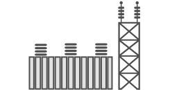
HV Substation Automation
Powerful substation automation systems often handle numerous communication protocols and media within one network, which can result in expensive and complex projects. Avoid these problems with interoperable technology and smart configuration tools.
MV Distribution Grid Automation
It is often difficult to find the exact solution you need in a MV application, leading to higher costs than necessary. With our scalable and adaptable solutions you will be able to only pay for what you really need, without comprimising on quality or security.

Photovoltaic Power Station
Using an open and scalable SCADA system to monitor and control a PV plant comes with many benefits on several levels. Find out how advanced communication technology affects PV operation, maintenance, system design, investment security, profits…